
In On learning InnoDB: A journey to the core, I introduced the innodb_diagrams project to document the InnoDB internals, which provides the diagrams used in this post. Later on in A quick introduction to innodb_ruby I walked through installation and a few quick demos of the innodb_space command-line tool.
The physical structure of InnoDB’s INDEX pages was described in The physical structure of InnoDB index pages, and the logical structure was described in B+Tree index structures in InnoDB. Now we’ll look in detail at the physical structure of records used in those pages.
In this post, only COMPACT row format (for Barracuda table format) is considered.
Record offsets
In previous posts, record offsets have been described in many structures that need to “point” to records. Record offsets point to the start of the record data itself, which is variable-length, but each record is preceded by a record header, which is also variable-length. In this post and the illustrations in it, I use N to mean the start of the record, where the record data is at N and using positive offsets (e.g. N+1), and the record header uses negative offsets (e.g. N-1). InnoDB often refers to the start of the record data, location N as the “origin”.
The record header
In previous posts, the record header was mentioned a few times, but hasn’t been fully described. As above, the record header precedes the record itself, and is structured as follows:
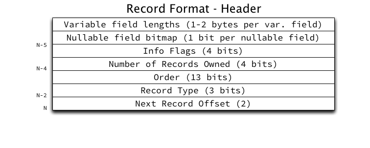
The fields in the record header are (in order, backwards from N):
- Next Record Offset: A relative offset from the current record to the origin of the next record within the page in ascending order by key.
- Record Type: The type of the record, where currently only 4 values are supported: conventional (0), node pointer (1), infimum (2), and supremum (3).
- Order: The order in which this record was inserted into the heap. Heap records (which include infimum and supremum) are numbered from 0. Infimum is always order 0, supremum is always order 1. User records inserted will be numbered from 2.
- Number of Records Owned: The number of records “owned” by the current record in the page directory. This field will be further discussed in a future post about the page directory.
- Info Flags: A 4-bit bitmap to store boolean flags about this record. Currently only two flags are defined: min_rec (1) meaning this record is the minimum record in a non-leaf level of the B+Tree, and deleted (2) meaning the record is delete-marked (and will be actually deleted by a purge operation in the future).
- Nullable field bitmap (optional): A single bit per nullable field to store whether the field is NULL, rounded up to a whole number of bytes. If a field is NULL its field value will be eliminated from the key or row portion of the record. If no fields are nullable, this bitmap is absent.
- Variable field lengths array (optional): An array of 8-bit or 16-bit integers (depending on the maximum size of the field) per variable-length field to store the length of the field data for that field. If no fields are variable-length, this array is absent.
The record header is a minimum of 5 bytes per row, but for records with many variable-width fields, it could be a lot larger.
Clustered indexes
The clustered key (PRIMARY KEY) has one of the more complex record structures:
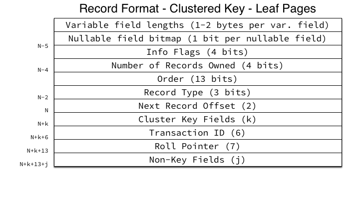
The following fields are included in the record data:
- Cluster Key Fields: The cluster key fields, concatenated together (literally). InnoDB just concatenates the raw bytes of its internal storage formats per column type together into a single byte stream.
- Transaction ID: The 48-bit integer transaction ID of the transaction which last modified this record.
- Roll Pointer: A structure containing information about the location in the rollback segment of the undo records for the transaction which last modified this record. The fields of the roll pointer structure are: 1-bit “is insert” flag, 7-bit rollback segment ID, 4-byte page number and 2-byte page offset of the undo log location.
- Non-Key Fields: All non-key fields (the actual row data for all non-PRIMARY KEY fields) concatenated together into a single byte stream.
The structure of non-leaf page records is similar, but somewhat simpler:

Since non-leaf pages are not MVCC, the Transaction ID and Roll Pointer fields are eliminated. Instead of the non-key fields, the child page number this node pointer points to is included. Since the cluster key cannot be NULL, the nullable field bitmap is absent.
Secondary indexes
Secondary indexes in InnoDB have an identical overall structure to the clustered key (PRIMARY KEY) but instead of containing non-key fields, they contain the clustered key fields, also known as a Primary Key Value or most commonly, PKV. If any fields overlap between the secondary key and the clustered key, the overlapping fields are removed from the clustered key stored in the secondary index records. For example, if a table has a PRIMARY KEY (a, b, c) and a secondary index KEY (a, d), the secondary key in the index will be as expected, (a, d) but the PKVs will contain only (b, c).
Since secondary keys are allowed to include fields that are both non-unique and nullable, both the variable field lengths array and the nullable field bitmap may be present if necessary. Otherwise the leaf page structure is very simple:
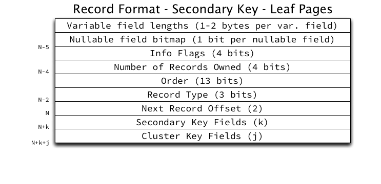
The secondary key fields are concatenated together into a single byte stream as with the clustered key. The clustered key fields are concatenated together in exactly the same way to form the PKV.
The secondary index non-leaf pages will also look familiar:
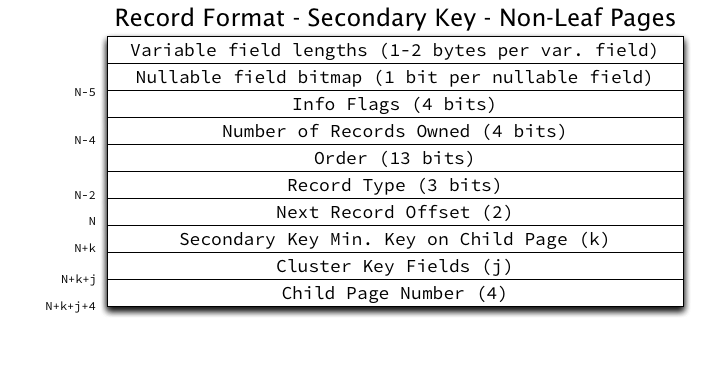
There is one thing of note for secondary index non-leaf pages: the clustered key fields (PKV) are included in the record and is considered part of the record’s key, not its value. Secondary indexes may be non-unique, but each record in the page must have a unique identifier, so the PKV must be included in the record to ensure uniqueness. This will mean that records in non-leaf pages of secondary keys will be 4 bytes larger than their leaf page counterparts.
An aside on per-row overhead
Looking at the above illustrations, you can easily calculate the per-row overhead InnoDB requires. Clustered Key Leaf Pages require a minimum of 5 bytes for the header, 6 bytes for the Transaction ID, and 7 bytes for the Roll Pointer, totaling 18 bytes per row. For very narrow tables (for example 2-3 integers) this overhead can be quite high.
In addition, there is substantial per-page overhead, and waste in inefficiently filling pages which can consume large amounts of space (for instance pages may be half-filled).
What’s next?
In the next post I will describe the page directory and its purpose in efficient record retrieval.
Update: I had incorrectly stated that the nullable field bitmap would not be present on clustered key leaf pages, but it is in fact present if any non-key fields are nullable. It is always absent on clustered key non-leaf pages because the clustered key must be NOT NULL.

Jeremy,
Suppose I have the following table:
CREATE TABLE t1 (a int, b int, c int, d int, PRIMARY KEY (a,b.c), KEY idx(d,b));
What records will be in the leaf pages of the secondary key idx:
d,b,a,c
or
d,b,a,b,c?
Regards,
Igor.
Igor: Great question, and worth addressing in the post itself. In short, the secondary key will contain “d,b,a,c” (the PKV will not duplicate the secondary key fields). I have added the following to the post:
“If any fields overlap between the secondary key and the clustered key, the overlapping fields are removed from the clustered key stored in the secondary index records. For example, if a table has a PRIMARY KEY (a, b, c) and a secondary index KEY (a, d), the secondary key in the index will be as expected, (a, d) but the PKVs will contain only (b, c).”
Jeremy,
Thanks,
Igor.
I’m handling TPC-H lineitem table.
The record format of this table doesn’t seem to “Clustered key leaf pages”.
Especially, it has null bitmap right after variable length fields.
Lineitem has 16 columns, however, data dictionary tells me that it has 18 columns, because TID and Roll pointer are added to this record.
Anyway in my case “Clustered key – leaf pages” also can have null bitmaps.
Sorry for the delay in responding to this — yes, they do also have nullable field bitmaps. I have updated the diagrams.
Since the clustered index key leaf pages also contain non-key row data won’t they include a nullable field bitmap to encode which nullable row fields are null? I understand that cluster index key (primary keys) can’t include any nullable fields, so non-leaf clustered index pages won’t have a bitmap, but row fields could be null and those are stored in the leaf pages.
Sorry for the delay in responding to this — yes, they do also have nullable field bitmaps. I have updated the diagrams.
Hi, Jeremy,
When I read the official document of Innodb of MySQL, I found the following contents on:
http://dev.mysql.com/doc/refman/5.6/en/innodb-persistent-stats.html
—-
If a balance cannot be achieved between accurate statistics and ANALYZE TABLE execution time, consider decreasing the number of indexed columns in the table or limiting the number of partitions to reduce ANALYZE TABLE complexity. The number of columns in the table’s primary key is also important to consider, as primary key columns are appended to each non-unique index.
—–
and the following content on:
http://dev.mysql.com/doc/refman/5.6/en/innodb-analyze-table-complexity.html
——–
In Big O notation, ANALYZE TABLE complexity is described as:
O(n_sample
* (n_cols_in_uniq_i
+ n_cols_in_non_uniq_i
+ n_cols_in_pk * (1 + n_non_uniq_i))
* n_part)
where:
n_sample is the number of pages sampled (defined by innodb_stats_persistent_sample_pages)
n_cols_in_uniq_i is total number of all columns in all unique indexes (not counting the primary key columns)
n_cols_in_non_uniq_i is the total number of all columns in all non-unique indexes
n_cols_in_pk is the number of columns in the primary key (if a primary key is not defined, InnoDB creates a single column primary key internally)
n_non_uniq_i is the number of non-unique indexes in the table
n_part is the number of partitions. If no partitions are defined, the table is considered to be a single partition.
CREATE TABLE t (
a INT,
b INT,
c INT,
d INT,
e INT,
f INT,
g INT,
h INT,
PRIMARY KEY (a, b),
UNIQUE KEY i1uniq (c, d),
KEY i2nonuniq (e, f),
KEY i3nonuniq (g, h)
);
SELECT index_name, stat_name, stat_description
FROM mysql.innodb_index_stats
WHERE
database_name=’test’ AND
table_name=’t’ AND
stat_name like ‘n_diff_pfx%’;
+————+————–+——————+
| index_name | stat_name | stat_description |
+————+————–+——————+
| PRIMARY | n_diff_pfx01 | a |
| PRIMARY | n_diff_pfx02 | a,b |
| i1uniq | n_diff_pfx01 | c |
| i1uniq | n_diff_pfx02 | c,d |
| i2nonuniq | n_diff_pfx01 | e |
| i2nonuniq | n_diff_pfx02 | e,f |
| i2nonuniq | n_diff_pfx03 | e,f,a |
| i2nonuniq | n_diff_pfx04 | e,f,a,b |
| i3nonuniq | n_diff_pfx01 | g |
| i3nonuniq | n_diff_pfx02 | g,h |
| i3nonuniq | n_diff_pfx03 | g,h,a |
| i3nonuniq | n_diff_pfx04 | g,h,a,b |
+————+————–+——————+
——–
From the above content, it seems that the physical structure of a unique index is different from a non unique index in that a unique index does not contain the primary key fields. What’s the physical structure of the unique index and now that it does not have the primary key fields, how does MySQL use it to find a non key field value of a row?
Hi Jeremy,
Great article.
As I understand it, InnoDB uses B+tree , which, based on wikipedia, only store key on the non-leaf nodes.
However, your article seams state otherwise. Please advise.
Thanks a lot in advance
James