Note: This article is the 3rd in a series of posts about electronics.
Once you have all of the hardware you’re going to need, you’re ready to get the software set up! But wait! Maybe you should understand the hardware architecture a bit better, as it quickly starts to matter when you’re writing programs.

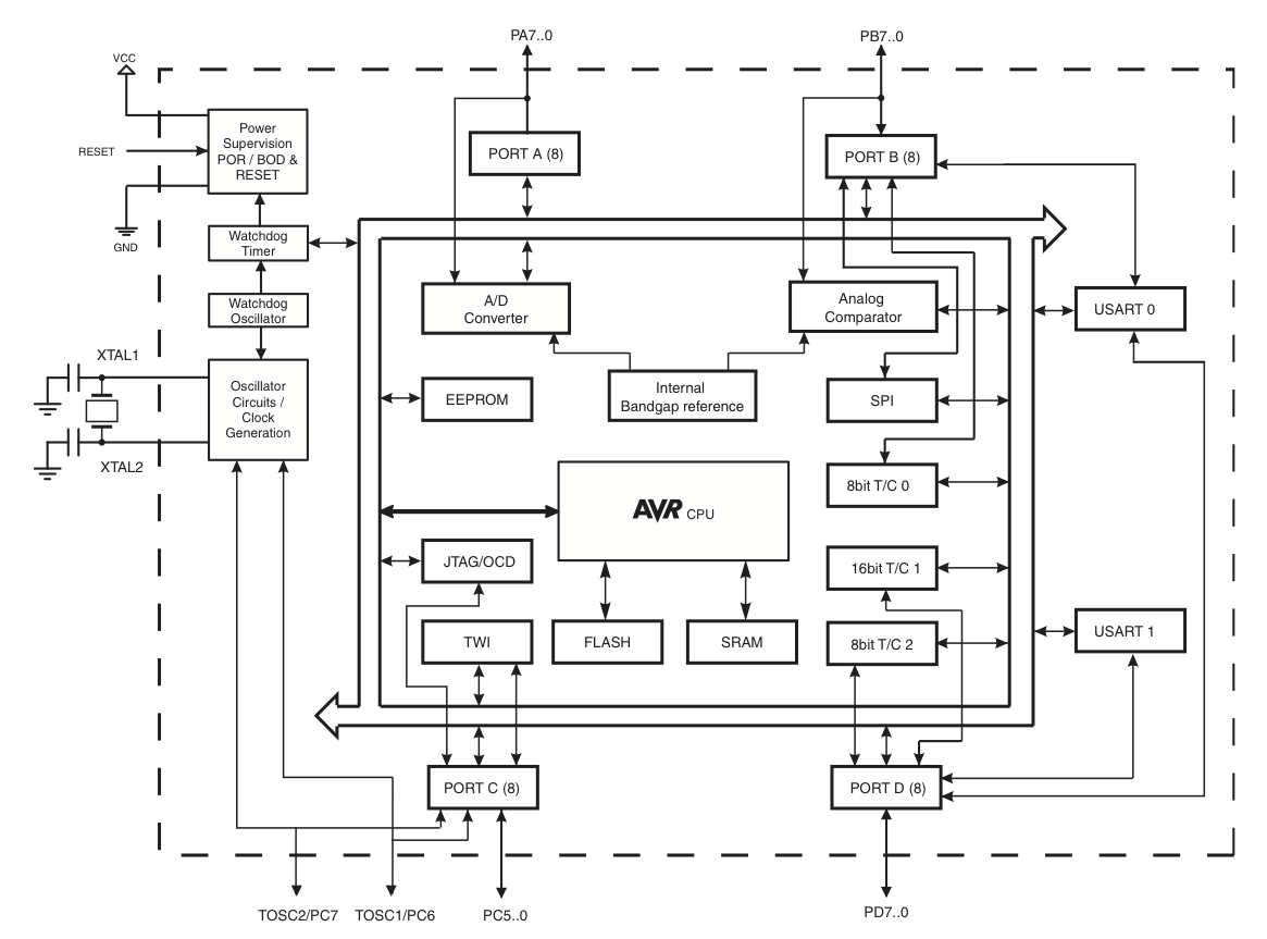
AVR Architecture Block Diagram (from ATmega644PA). The Flash, SRAM, and peripheral buses are all separately connected to the CPU.
The AVR memories
The AVR architecture makes use of four different types of memories:
Flash
Flash memory, or just flash, is erasable, non-volatile storage (it doesn’t require any refreshes to keep storing data) used for program storage. When you have compiled a program and you upload it to the device, this is where it’s stored. When your program runs, it is run directly from the flash memory (it is not copied into RAM as most PCs would do).
SRAM
Static RAM (SRAM) is used for transient program state (such as variables) as well as the program stack and any allocations made by the program. When the program starts, all global variables are initialized in SRAM by a special routine generated automatically by the compiler. The AVR architecture does not inherently or automatically reset memory, so without explicit resets by the program (usually automatic) the memory contents is persistent across resets. (This fact can actually be utilized by the program by allocating variables in the “.noinit” section.)
EEPROM
EEPROM (electrically erasable, programmable, read-only memory) is used for non-volatile persistent storage. It is a good place to write configuration values (such as baud rates, unique IDs, etc.), to keep track of counters over a long term, and to keep static data that isn’t needed frequently. Accessing EEPROM memory requires special instructions and is quite slow compared to SRAM, and can be risky if the device loses power (the data can be corrupted). Due to the limited number of writes that EEPROM can handle (approximately 100,000) before failure, care should be taken not to write unnecessarily.
Fuses
In addition to the Flash, SRAM, and EEPROM, AVRs have a few bytes (usually 3) of fuse memory. This memory is used to store “fuse bytes”, which are boot-time configuration values used to initialize the microcontroller itself. On systems that have 3 bytes, such as the ATmega644, they are called “low”, “high”, and “extended” (or “l”, “h”, and “e”), and they each store individual bits or bit values of configuration settings. For example, you use fuses to set the clock input source (CKSEL[0..3]), whether the clock should be divided by 8 (CKDIV8), whether the watchdog timer, SPI, and JTAG should be enabled (WDTON, SPIEN, JTAGEN respectively), and many other important things.
The Harvard architecture
Modern PCs are based on the von Neumann architecture, which uses a CPU and a single memory (generally DRAM) attached by a single bus, which is used for program memory and data memory. In contrast, the Harvard architecture, which is used by the AVR, uses entirely separate buses and memories for program and data memory. This allows for higher performance as well as to allow the program and data buses to be different widths.
Aspects of the Harvard architecture are visible to the programmer in a way which is normally not considered when writing programs for the PC:
- Static values must be copied from program memory to data memory in order to be used by the program in most contexts. This impacts initializers as well as any strings or structures you may use in the program.
- It’s possible to use functions to minimize memory usage by copying values (especially strings) from program memory directly to IO channels such as serial output, and this is exposed to the user in the form of PROGMEM declarations and *_p variants of many different functions.
- Pointers are not all equal. There are pointers to program memory, and pointers to data memory. You cannot mix the two.
Peripherals and pin-sharing
While each AVR generally offers a large number of peripherals, you may have to choose which ones you are able to use based on which pins are shared on the particular device in question. For instance, if you need a large number of GPIO pins, you may not be able to use an external oscillator, you may have to choose between using timers for internal timekeeping versus PWM, etc.
The datasheets are essential for understanding which pins share which functions. In general, the higher pin count devices share less pins between functions, and in fact Atmel offers several devices in lower- and higher-pin-count versions (for instance ATmega1280 [100-pin] versus the ATmega1281 [64-pin]); the same device with more or less pins shared.
The datasheets typically have a section titled “Alternate Port Functions” which does a very good job of describing all of the pin-sharing on each device.
Clock systems, clock sources, and oscillators
Clock systems

AVR Clock Distribution Block Diagram. Clock sources supply the AVR Clock Control Unit via a prescaler, and are then distributed to the various clock system components.
The AVR architecture has several different clock sources, which can be independently halted:
- clkCPU — The main AVR core clock used for most instruction processing.
- clkI/O — Most peripherals operate from this clock, such as timers, SPI, and the USART.
- clkFLASH — Reading and writing from the flash memory used this clock, which is usually synchronized with clkCPU.
- clkASY — This clock can be set up to clock the real-time timer/counter independently of all other clock sources to allow for unimpeded clocking if necessary, even in power-saving modes.
- clkADC — The analog-to-digital conversions operate from this clock to allow the other clocks to be halted during conversions to eliminate noise.
Clock sources
One of the most important decisions when setting up a microcontroller is its clkCPU clock source. Typically, AVR microcontrollers offer several clock sources:
- Internal 8MHz oscillator (pre-scaled by 1/8 to 1MHz by default)
- Internal 128kHz oscillator (for power-saving)
- External crystal oscillator up to 20MHz
- External clock signal (typically from another microcontroller)

AVR Clock Generation. The internal oscillators can be used, but typically an external crystal oscillator is connected across XTAL1 and XTAL2, with a pair of 18pF capacitors to ground.
Prescalers
All of the clock inputs are fed into a prescaler which can scale the clock by anywhere from 1 (no scaling) to 256 (256 cycles of the oscillator to one cycle of the clock). Typically the prescaler is set at run-time, as necessary, to reduce the clock speed, thus saving power by executing less. There is one special way the prescaler is set: a fuse called CKDIV8 can, if set, automatically prescale the clock by 1/8 at boot time. This is used for the default configuration to prescale the 8MHz internal clock to 1MHz.
Oscillators and the choice of frequencies
If you choose to use an external oscillator, you have to choose the frequency. It’s not immediately obvious what the best frequency would be. In reality, the best frequency is usually driven by the application: performance requirements, interoperability with other systems, and communications requirements. There are a few frequencies which are in wide-spread use:
- 1MHz — The on-board prescaled frequency, which is not terribly fast, but saves a lot of power.
- 8MHz — The on-board non-prescaled frequency, which is generally fast enough and doesn’t require external components.
- 14.7456MHz — Why in the world such a specific frequency? There’s a simple answer: standard baud rates, such as 9600, 38400, and 115200 baud, can all be perfectly generated by a microcontroller running at this frequency.
- 16MHz — A quite fast frequency which is still very compatible with various baud rates, especially if you have control over the baud rate.
- 20MHz — If you want maximum performance and you control the baud rate, max out the clock speed.